NRF24L01: the cheap 2.4 GHz radio that actually works in the field — if you know where it hides
A year of debugging the wrong thing
For months, my wireless chronometer kept dropping data intermittently. Sensors would stop communicating. The display would freeze. I suspected the cables first — checked every connection, re-soldered every joint. Then the power supply. Then the code. I rebuilt parts of the firmware. I swapped modules. Nothing worked consistently.
Over a year later, I finally found the cause.
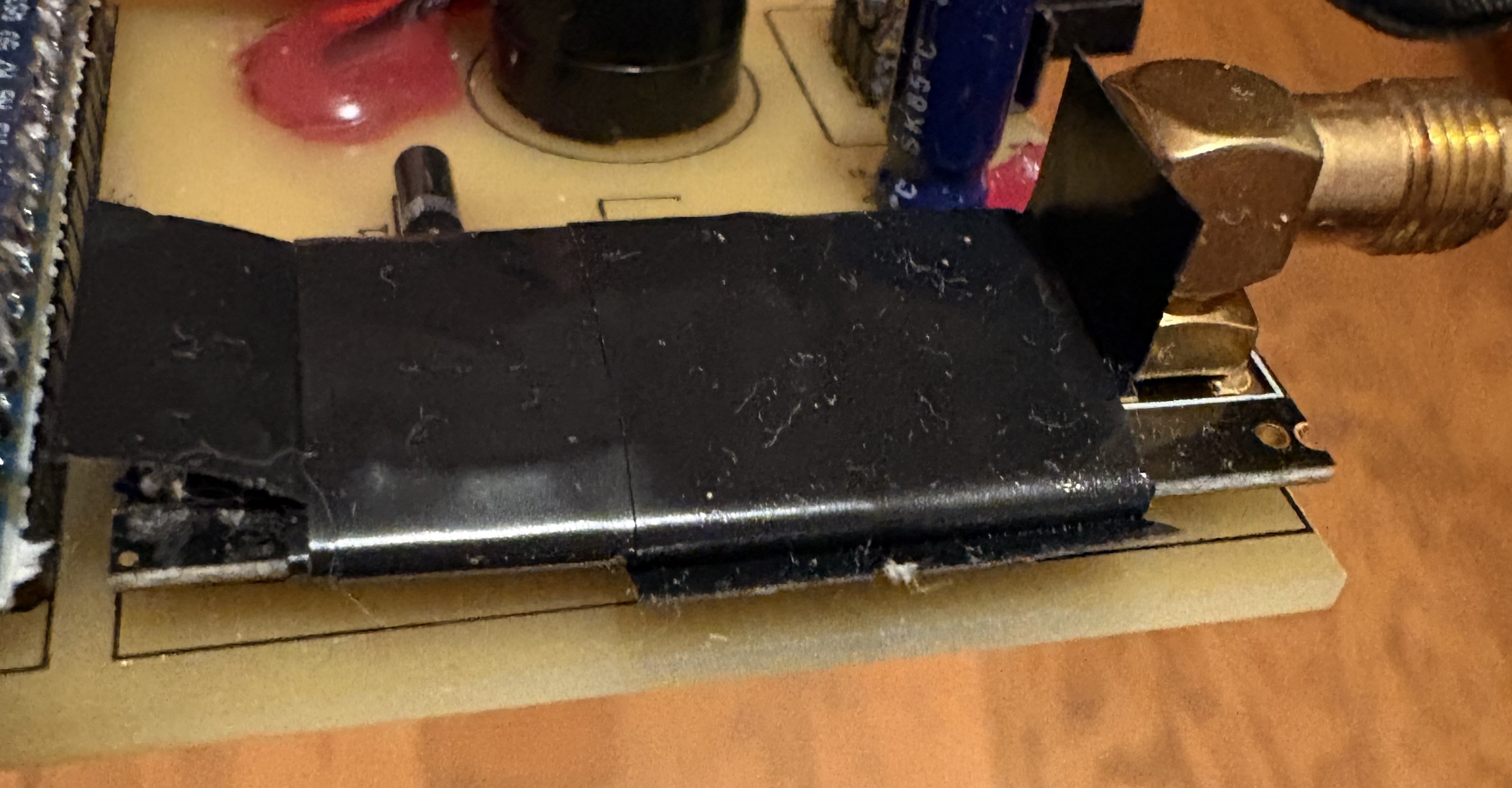
The PCB that the NRF24 module was mounted on was generating electromagnetic interference. The antenna — sitting a few millimetres from active circuitry — was picking up noise from its own board. The fix took about ten minutes: a small shield of aluminium foil wrapped around the module, grounded to the board.
The system has worked reliably ever since.
That experience is the most useful thing I can tell you about the NRF24L01 before anything else. The module itself is excellent. The failure mode that will drive you insane is rarely the radio — it’s almost always the environment you put it in.
What the NRF24L01 is
The NRF24L01 is a single-chip 2.4 GHz radio transceiver made by Nordic Semiconductor. You’ll find it on small breakout modules that cost around one or two euros per piece — the kind of price point that makes you buy ten at a time without thinking about it.
It communicates with a microcontroller over SPI, which means four wires and a chip-select line. It handles everything radio-related internally: packetising your data, adding error-checking, sending automatic acknowledgments, retransmitting if a packet is lost. From the microcontroller’s perspective, you write a payload into a buffer and tell it to transmit. The module handles the rest.
The data rate is configurable — 250 kbps, 1 Mbps, or 2 Mbps — and so is the transmission power. Lower data rates give better range and noise immunity; higher rates suit scenarios where you’re sending frequent updates over short distances. For most sport-tech field applications, 1 Mbps at moderate power is a reasonable default.
One feature worth knowing upfront: a single NRF24 receiver can listen on up to six independent data pipes simultaneously. Each pipe has its own address, and the module automatically routes incoming packets to the right pipe. This is what makes the master-slave topology work cleanly — one receiver can hear from multiple sensors without any additional coordination layer.
Why NRF24 for sport-tech field devices
The obvious alternatives are BLE (Bluetooth Low Energy), ESP-NOW, and LoRa. Each has its place, but for devices that need to work reliably outdoors, across a sports field, with multiple nodes, the NRF24 has a combination of properties that’s hard to beat.
It’s fast. At 2 Mbps it can push updates at a rate that matters for real-time timing applications. BLE has higher latency by design — it’s optimised for power efficiency and connection management, not raw throughput.
The range is sufficient for field sport. A standard NRF24L01 module reaches reliably across a typical training area. The PA+LNA version — which adds a power amplifier and a low-noise amplifier, usually paired with an external antenna — extends that range significantly for larger venues or when you need to place sensors further apart.
The library ecosystem is mature. The RF24 library for Arduino and compatible microcontrollers is well-documented, actively maintained, and handles the lower-level radio management cleanly. You configure the module in a few lines, define your network topology, and start sending and receiving data. The learning curve is short.
It doesn’t require pairing, negotiation, or connection state. BLE devices need to discover and pair. The NRF24 just listens or transmits to a fixed address. For a timing system where multiple photocells need to be operational the moment you power them on, this simplicity is genuinely useful.
LoRa is the better choice when you need very long range (hundreds of metres to kilometres) or very low power over extended battery life. For a sport-tech device operating within a single training facility or athletics track, LoRa is more than you need and the hardware is considerably more expensive.
The hardware mistake that will cost you time
The NRF24L01 is sensitive to its power supply and to electromagnetic interference in its immediate surroundings.
On the power supply side, the module draws current in brief spikes during transmission. If the supply line isn’t adequately decoupled, these spikes cause voltage drops that destabilise the radio. The standard fix — adding a 100 µF capacitor between the module’s VCC and GND pins, physically close to the module — resolves most power-related instability. This is the first thing to try when the module behaves erratically.
On the interference side, the NRF24’s antenna is small and close to the board. If your PCB has switching regulators, motor drivers, or other sources of high-frequency noise anywhere near the module, those signals couple into the antenna and corrupt reception. This is what caused my year of phantom debugging: the chronometer’s own PCB was generating interference that the NRF24 was interpreting as noise on the radio channel.
The fix that worked for me was shielding: a small enclosure of aluminium foil around the NRF24 module, with the foil connected to ground. It’s not elegant, but it’s effective, and it costs nothing. If you’re designing a PCB from scratch, the cleaner solution is to physically separate the NRF24 from any high-frequency circuitry and give it a dedicated ground plane. Either way, the principle is the same: the antenna needs a quiet electromagnetic environment to work reliably.
If your NRF24 is dropping packets, freezing, or behaving inconsistently, suspect the hardware environment before the module itself. Check power supply decoupling first. Check for interference sources second. The radio is almost certainly fine.
Building a sensor network: master and slaves
The NRF24 is designed for point-to-point communication, but with a bit of addressing it maps naturally onto a star topology: one master listening, multiple slaves transmitting.
In my chronometer, the display unit acts as master. Each photocell gate is a slave. Every slave has a unique address assigned at setup — written into a dedicated pipe on the master’s receiver. When a photocell is triggered, it transmits a packet to the master’s address. The master receives it, identifies which pipe it came from (and therefore which gate triggered), and uses that to calculate split times or the final elapsed time.
The master never broadcasts and the slaves never listen to each other. Each slave just transmits to the master when something happens. This simplicity is a feature: there’s no routing protocol, no collision avoidance to manage manually, no state to maintain between events. The NRF24’s built-in auto-acknowledgment handles retransmission if a packet is lost. The application code stays clean.
This architecture scales naturally. Adding another gate is adding another slave with a new address. As long as you stay within the six-pipe limit of a single NRF24 receiver, no changes to the master are needed.
What this is building toward
The wireless chronometer is a project I’ve been working on for a while — custom PCB, 3D-printed gate housings, multiple timing points, split times displayed in real time. It’s the kind of device that doesn’t exist off the shelf at a price that makes sense for training environments, which is exactly why I built it.
I’ll cover it in detail in an upcoming multi-part series: the hardware design, the PCB layout decisions, the 3D printing iterations, and the firmware. The NRF24 is one piece of that system — the piece that lets the gates talk to the display without anyone running cables across a track.
If the previous articles on VBT, accommodating resistance, and IMU sensor fusion gave you the sport-science and sensor-side foundations, the chronometer series is where a complete field measurement system comes together.

Lodovico Cortelazzo
Former national-team athlete. 15 years of training. Exercise science and engineering.
Fifteen years of training, eight at national level, give a specific kind of eye for what sport technology actually does versus what it claims to do. I combine a background in exercise science with hands-on engineering to build and analyse tools that are meant to work in the real world. If you are working on something in this space and want that perspective, reach out.
Work with me →