How I Turned a Cheap Alarm Clock Into a Heads-Up Display for My Runs (Part 2)
Part 2 — and the final one. If you haven’t read Part 1, start there: it covers the problem, the BLE heart-rate setup, and how I cracked the projector module open to find the TM1621D chip.
Connecting the wires
Before the story, there’s hardware to set up. The projector ribbon has seven wires — one red, six grey. Here’s how they map to the ESP32:
| Wire | Colour | Signal | ESP32 pin | Notes |
|---|---|---|---|---|
| 0 | Red | GND | GND | Power ground |
| 1 | Grey | — | GPIO 12 | Button |
| 2 | Grey | CS | GPIO 21 | Chip select (latchPin) |
| 3 | Grey | WR | GPIO 22 | Clock (clkPin) |
| 4 | Grey | DATA | GPIO 23 | Serial data (dataPin) |
| 5 | Grey | 4.7V | 5V / VIN | Power |
| 6 | Grey | GND | GND | Button ground |
Pin 12 — a free button. Analysing the circuit, I noticed that wire 1 wasn’t used for display driving at all once the module was detached from the main board — it floated freely. I repurposed it as INPUT_PULLUP (the pin stays HIGH by default; pressing a button pulls it LOW), which gave me a button with no extra wiring. The two GNDs have different roles: wire 0 is the power return for the display, wire 6 is the reference for the button.
Power. Rated for 4.7V, runs fine on the ESP32’s 5V VIN pin. I never had a stability issue.

The vocabulary problem
At the end of Part 1, I had something I called the Holy Grail — lcdShift(), a function that could push any 13-bit pattern into the TM1621D over a 3-wire interface. Physically, I owned the chip. I could make something happen on that wall.
Why 13 bits? The TM1621D’s write command has a fixed structure: 3 bits for the opcode (which operation you’re asking for), 6 bits for the address (enough to index the chip’s 64 internal RAM cells), and 4 bits for the data nibble (which segments to light). 3 + 6 + 4 = 13. The command width isn’t arbitrary — it’s the exact sum of those three fields.
The problem was I had no idea what to say. I knew the frame, but not the content. What nibble makes a 3? What address targets the leftmost digit? Anything at all?
That question took the better part of a month to fully answer.
The datasheet nobody translated
The TM1621D has a datasheet. It’s entirely in Chinese.
I don’t read Chinese. So I did what any engineer does when the words are useless: I ignored them entirely and looked at the structure. Datasheets follow a universal grammar regardless of language — tables have rows and columns, binary values mean binary values, and a block of bits in the right-hand column is always telling you something about operation modes.
There was one table I kept coming back to.
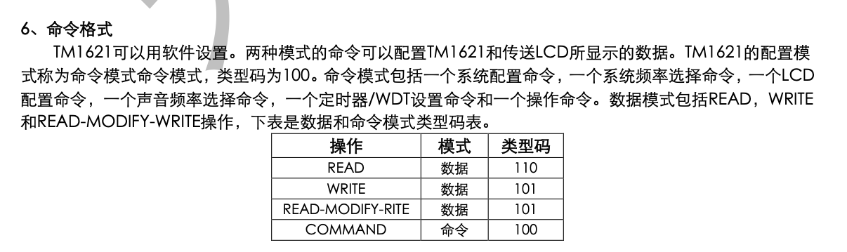
Three operation types, each identified by a 3-bit code. The row with 101 pointed to a data write operation. So the skeleton of each command looked something like this:
[101] [address] [com]
 ^^^    ^^^^^    ^^^
write   which   which
        cell   segments
How many bits for address? How many for com? What did writing to a given address actually do to the segments? That I still didn’t know.
Before resorting to brute force, I found a project on Hackster.io where someone had done something similar — Custom Output from Alarm Clock Ceiling Projector. I read just enough to confirm the project was possible, then closed the tab deliberately. I wanted to find the segment map myself. For me, that was the whole point.
Four hours of nothing
I want to be honest about what the next few hours looked like, because most write-ups skip this part.
Armed with the opcode 101 and not much else, I started sending commands. I varied the address width, the data width, the bit ordering, the timing. The display stayed frozen in its garbled startup state. Nothing moved.
After a couple of hours I stopped guessing and went systematic. I wrote a function that swept through all combinations of address and data nibble automatically — a nibble is just 4 bits, the lower half of a byte — pausing after each command so I could watch the wall:
void segmentsTest() {
  for (int coms = 8; coms < 17; coms++) {
    clearAll();
    for (int address = 14; address < 25; address++) {
      unsigned long cmd = (0b101 << 10) | (address << 4) | coms;
      lcdShift(cmd, 13);
      delayMicroseconds(50);
      Serial.print("address = "); Serial.println(address);
      Serial.print("coms = "); Serial.println(coms);
      waitForOK(); // pauses until I press Enter in the Serial monitor
    }
  }
}
Each command packs three things into 13 bits: the 101 opcode at the top, the address in the middle, and a 4-bit nibble at the bottom. waitForOK() meant I stepped through manually, one command at a time, eyes on the projector.
I pressed Enter for two more hours.
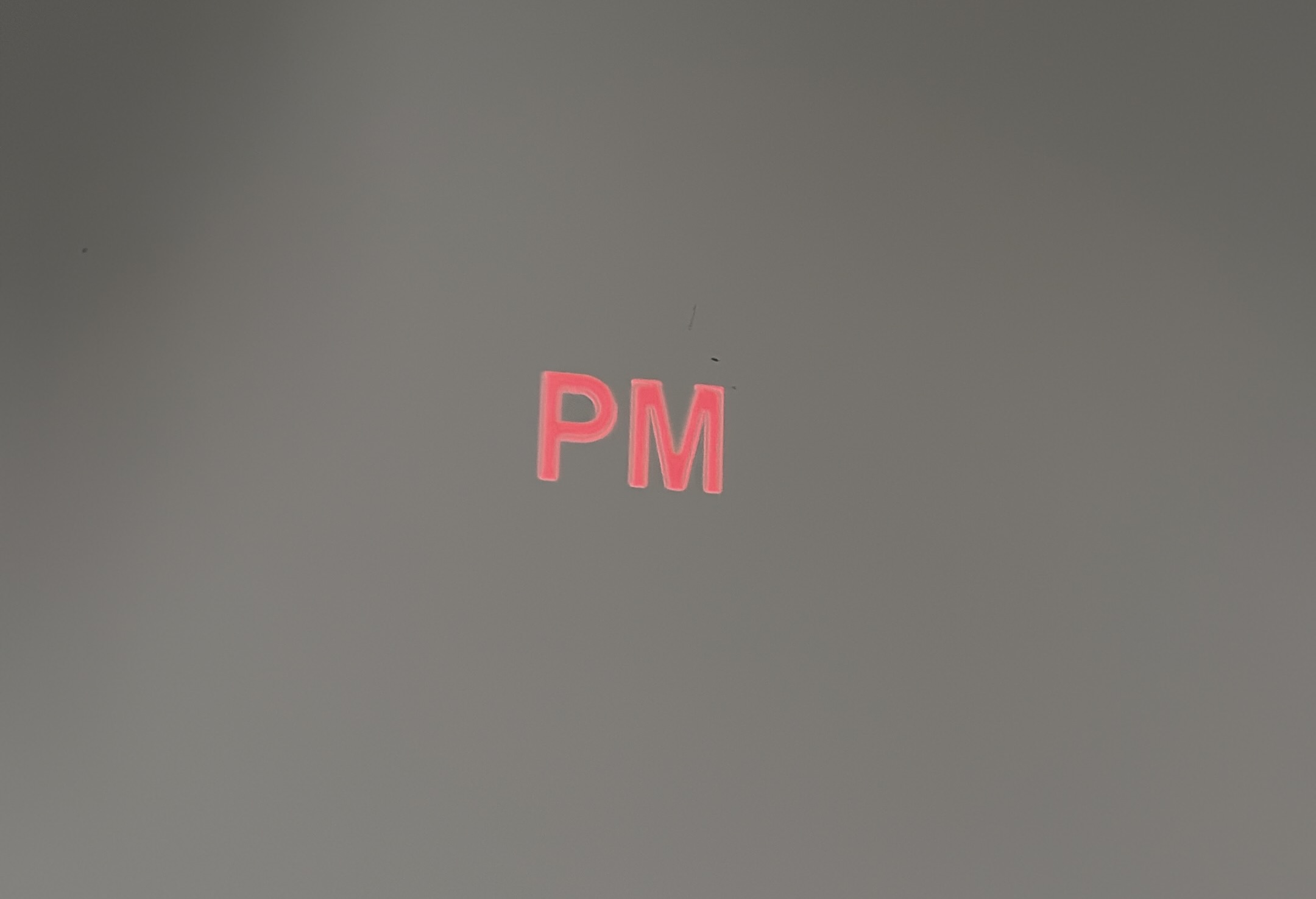
PM
Then, at some combination I hadn’t consciously anticipated, something moved.
Not a digit. Not anything I’d asked for. Just PM — that small indicator in the corner of the display, the one that tells you whether the clock reads 3 in the afternoon or 3 in the morning.
It doesn’t sound like much. But after four hours of absolute silence, a single segment toggling on the wall was everything. It meant the protocol was right. The opcode was right. The bit width was right. The framing was right.
I had the language. I just didn’t have the dictionary yet.
Half a day with a notebook
Once segmentsTest() could move individual segments, I knew exactly what I had to do: map every single one. A seven-segment display is seven independently controllable bars — write the right nibble to the right address and they light up to form a digit. I just needed to find which nibble and which address did what, for all ten digits.
Here’s how the addressing worked for this specific display:
Address = which digit position. COM nibble = which bars light up.
The display has four digit slots. Each slot is controlled by a pair of consecutive RAM addresses:
| Digit | Addresses |
|---|---|
| 1 — leftmost | 21, 22 |
| 2 | 19, 20 |
| 3 | 17, 18 |
| 4 — rightmost | 15, 16 |
Each address stores a 4-bit nibble. Each bit maps to one physical bar. Set a bit to 1 and the bar lights up. Set it to 0 and it goes dark.
After mapping every digit this way — and filling several pages of my notebook in the process — the complete table looked like this:

Example: the number 3.
The digit 3 needs five bars: top, top-right, middle, bottom-right, bottom. Working through the sweep data, those bars appeared at:
- Address
15: two separate nibble values — COM0b0111and COM0b1000— each lighting up different bars of the same digit. Since they target the same address, I OR them:0b0111 | 0b1000 = 0b1111. - Address
14: COM0b0001, which controls the bottom bar.
So to show a 3: write 0b1111 to address 15, write 0b0001 to address 14. The shiftDigit() function in the code adds the right offset automatically depending on which of the four digit positions we’re targeting.
int numbersMap[10][2][2] = {
  {{15, 0b1101}, {14, 0b0111}},  // 0
  {{15, 0b0101}, {0,  0b0000}},  // 1
  {{15, 0b1110}, {14, 0b0011}},  // 2
  {{15, 0b1111}, {14, 0b0001}},  // 3
  {{15, 0b0111}, {14, 0b0100}},  // 4
  {{15, 0b1011}, {14, 0b0101}},  // 5
  {{15, 0b1011}, {14, 0b0111}},  // 6
  {{15, 0b1101}, {0,  0b0000}},  // 7
  {{15, 0b1111}, {14, 0b0111}},  // 8
  {{15, 0b1111}, {14, 0b0101}},  // 9
};
1 and 7 only need one write — the second entry is {0, 0} and gets skipped. Everything else takes two.
This is the entire reverse-engineering effort distilled to 10 lines.
The final firmware
With the segment map working, everything else was implementation. The firmware does three things:
- Connects to a BLE heart-rate strap and reads live BPM, smoothed over a 50-sample rolling average.
- Drives the display in either Heart Rate or Stopwatch mode.
- Reads the button on GPIO 12 with a small state machine: single click starts/pauses the stopwatch, double click switches modes, long press resets the timer.
Three things, one button, no screen.
Show full source code
#include <BLEDevice.h>
#include <BLEUtils.h>
#include <BLEScan.h>
#include <BLEClient.h>
#include <Arduino.h>

// --- Pin definitions ---
#define latchPin 21  // CS
#define clkPin   22  // WR
#define dataPin  23  // DATA

// --- BLE ---
BLEScan* pBLEScan;
BLEAdvertisedDevice* heartRateDevice = nullptr;
const BLEUUID heartRateServiceUUID((uint16_t)0x180D);
const BLEUUID heartRateCharUUID((uint16_t)0x2A37);
bool connected = false;
BLERemoteCharacteristic* pRemoteCharacteristic;

// --- HT1621 init commands ---
unsigned long lcdOn    = 0b100000000110;
unsigned long lcdOff   = 0b100000000100;
unsigned long sysEn    = 0b100000000010;
unsigned long rc256k   = 0b100000110000;
unsigned long bias13x4 = 0b100001010010;
unsigned long normal   = 0b100111000110;

// --- Button ---
const int buttonPin = 12;
const unsigned long longPressThreshold = 2000;

// --- Mode ---
enum Mode { CARDIO, CRONOMETRO };
Mode currentMode = CARDIO;

// --- Stopwatch ---
bool running = false;
unsigned long startTime = 0;
unsigned long elapsed = 0;

// --- Heart rate smoothing ---
#define WINDOW_SIZE 50
int valori[WINDOW_SIZE];
int indice = 0;
bool bufferPieno = false;
int actualValue = 0;
int previousValue = -1;
int previousTimer = -1;

// --- Segment map ---
int numbersMap[10][2][2] = {
  {{15, 0b1101}, {14, 0b0111}},  // 0
  {{15, 0b0101}, {0, 0}},        // 1
  {{15, 0b1110}, {14, 0b0011}},  // 2
  {{15, 0b1111}, {14, 0b0001}},  // 3
  {{15, 0b0111}, {14, 0b0100}},  // 4
  {{15, 0b1011}, {14, 0b0101}},  // 5
  {{15, 0b1011}, {14, 0b0111}},  // 6
  {{15, 0b1101}, {0, 0}},        // 7
  {{15, 0b1111}, {14, 0b0111}},  // 8
  {{15, 0b1111}, {14, 0b0101}}   // 9
};

void lcdShift(unsigned long data, int bits) {
  unsigned long bitmask = 1UL << (bits - 1);
  digitalWrite(latchPin, LOW);
  for (int i = 0; i < bits; i++) {
    digitalWrite(clkPin, LOW);
    digitalWrite(dataPin, (data & bitmask) ? HIGH : LOW);
    delayMicroseconds(2);
    digitalWrite(clkPin, HIGH);
    delayMicroseconds(10);
    bitmask >>= 1;
  }
  digitalWrite(latchPin, HIGH);
  delayMicroseconds(2);
}

void clearAll() {
  for (int address = 0; address < 64; address++) {
    unsigned long cmd = (0b101 << 10) | (address << 4);
    lcdShift(cmd, 13);
    delayMicroseconds(50);
  }
}

void segmentLighter(unsigned long address, unsigned long coms) {
  unsigned long cmd = (0b101 << 10) | (address << 4) | coms;
  lcdShift(cmd, 13);
  delayMicroseconds(50);
}

unsigned long shiftDigit(unsigned long address, int digit) {
  unsigned long shifter = 0;
  if      (address == 14 && digit == 4) shifter = 2;
  else if (address == 14 && digit == 3) shifter = 0;
  else if (address == 14 && digit == 2) shifter = 6;
  else if (address == 14 && digit == 1) shifter = 8;
  else if (address == 15 && digit == 4) shifter = 2;
  else if (address == 15 && digit == 3) shifter = 0;
  else if (address == 15 && digit == 2) shifter = 4;
  else if (address == 15 && digit == 1) shifter = 6;
  else return address;
  return address + shifter;
}

void printSingleNumberHr(int number, int digit) {
  for (int i = 0; i < 10; i++) {
    if (number == i) {
      for (int c = 0; c < 2; c++) {
        unsigned long address = numbersMap[i][c][0];
        unsigned long com     = numbersMap[i][c][1];
        if (address != 0 && com != 0) {
          address = shiftDigit(address, digit);
          segmentLighter(address, com);
        }
      }
    }
  }
}

void printSingleNumberTimer(int number, int digit) {
  for (int i = 0; i < 10; i++) {
    if (number == i) {
      for (int c = 0; c < 2; c++) {
        unsigned long address = numbersMap[i][c][0];
        unsigned long com     = numbersMap[i][c][1];
        if (address != 0 && com != 0) {
          address = shiftDigit(address, digit);
          if (address == 20) com = com | 8;
          if (address == 19 && (number == 1 || number == 7)) segmentLighter(20, 8);
          segmentLighter(address, com);
        }
      }
    }
  }
}

int* splittaNumeroHr(int numero) {
  static int arr[5];
  char buffer[5];
  sprintf(buffer, "%d", numero);
  int len = strlen(buffer);
  for (int i = 0; i < len; i++) arr[i + 1] = buffer[i] - '0';
  for (int i = len + 1; i <= 4; i++) arr[i] = -1;
  return arr;
}

int* splittaNumeroTimer(int numero) {
  static int arr[5];
  char buffer[5];
  sprintf(buffer, "%04d", numero);
  int len = strlen(buffer);
  for (int i = 0; i < len; i++) arr[i + 1] = buffer[i] - '0';
  return arr;
}

void printNumberHr(int number) {
  int* cifre = splittaNumeroHr(number);
  for (int i = 1; i <= 4; i++) printSingleNumberHr(cifre[i], i);
}

void printNumberTimer(int number) {
  int* cifre = splittaNumeroTimer(number);
  for (int i = 1; i <= 4; i++) printSingleNumberTimer(cifre[i], i);
}

int aggiungiValore(int nuovoValore) {
  valori[indice] = nuovoValore;
  indice++;
  if (indice >= WINDOW_SIZE) { indice = 0; bufferPieno = true; }
  long somma = 0;
  int count = bufferPieno ? WINDOW_SIZE : indice;
  for (int i = 0; i < count; i++) somma += valori[i];
  return (int)(somma / count);
}

class MyAdvertisedDeviceCallbacks : public BLEAdvertisedDeviceCallbacks {
  void onResult(BLEAdvertisedDevice advertisedDevice) {
    if (advertisedDevice.haveServiceUUID() &&
        advertisedDevice.isAdvertisingService(heartRateServiceUUID)) {
      heartRateDevice = new BLEAdvertisedDevice(advertisedDevice);
      pBLEScan->stop();
    }
  }
};

void setupBLE() {
  BLEDevice::init("");
  pBLEScan = BLEDevice::getScan();
  pBLEScan->setAdvertisedDeviceCallbacks(new MyAdvertisedDeviceCallbacks());
  pBLEScan->setActiveScan(true);
  pBLEScan->start(10, false);
}

void leggiPulsante() {
  static bool btnPressedPrev = false;
  static unsigned long lastClickTime = 0;
  static int clickCount = 0;
  bool btnPressed = digitalRead(buttonPin) == LOW;
  unsigned long now = millis();

  if (btnPressed && !btnPressedPrev) {
    lastClickTime = now;
    clickCount++;
  }

  if (btnPressed && (now - lastClickTime > longPressThreshold)) {
    if (currentMode == CRONOMETRO) {
      running = false; elapsed = 0;
      clearAll(); printNumberTimer(0);
    }
    clickCount = 0;
  }

  if (!btnPressed && !btnPressedPrev && clickCount > 0 && (now - lastClickTime > 400)) {
    if (clickCount == 1 && currentMode == CRONOMETRO) {
      running = !running;
      if (running) startTime = millis() - elapsed;
      else elapsed = millis() - startTime;
    } else if (clickCount == 2) {
      currentMode = (currentMode == CARDIO) ? CRONOMETRO : CARDIO;
      clearAll();
      printNumberHr(actualValue);
    }
    clickCount = 0;
  }

  btnPressedPrev = btnPressed;
}

void aggiornaDisplayCronometro() {
  if (running) elapsed = millis() - startTime;
  int totalSeconds = elapsed / 1000;
  int actualTimer = (totalSeconds / 60) * 100 + (totalSeconds % 60);
  if (actualTimer != previousTimer) {
    clearAll(); printNumberTimer(actualTimer);
    previousTimer = actualTimer;
  } else {
    printNumberTimer(actualTimer);
  }
}

void aggiornaDisplayCardio() {
  if (actualValue != previousValue) {
    clearAll(); printNumberHr(actualValue);
    previousValue = actualValue;
  }
}

void setup() {
  Serial.begin(115200);
  pinMode(latchPin, OUTPUT);
  pinMode(clkPin, OUTPUT);
  pinMode(dataPin, OUTPUT);
  pinMode(buttonPin, INPUT_PULLUP);

  digitalWrite(latchPin, HIGH);
  digitalWrite(clkPin, LOW);
  digitalWrite(dataPin, LOW);

  delay(100);
  lcdShift(sysEn, 12);
  lcdShift(rc256k, 12);
  lcdShift(bias13x4, 12);
  lcdShift(lcdOn, 12);
  lcdShift(normal, 12);
  delay(50);
  clearAll();

  setupBLE();
}

void loop() {
  leggiPulsante();

  if (heartRateDevice && !connected) {
    BLEClient* pClient = BLEDevice::createClient();
    pClient->connect(heartRateDevice);
    BLERemoteService* pRemoteService = pClient->getService(heartRateServiceUUID);
    if (!pRemoteService) { heartRateDevice = nullptr; return; }
    pRemoteCharacteristic = pRemoteService->getCharacteristic(heartRateCharUUID);
    if (!pRemoteCharacteristic) { heartRateDevice = nullptr; return; }
    if (pRemoteCharacteristic->canNotify()) {
      pRemoteCharacteristic->registerForNotify(
        [](BLERemoteCharacteristic* c, uint8_t* data, size_t length, bool isNotify) {
          if (length > 1) actualValue = aggiungiValore(data[1]);
        }
      );
      connected = true;
    }
  }

  if (currentMode == CARDIO) aggiornaDisplayCardio();
  else aggiornaDisplayCronometro();

  delay(50);
}
Three things worth noting:
Smoothing. Raw BLE heart-rate values jump, especially on first connect. The 50-sample rolling average keeps the display stable without lagging behind real effort changes.
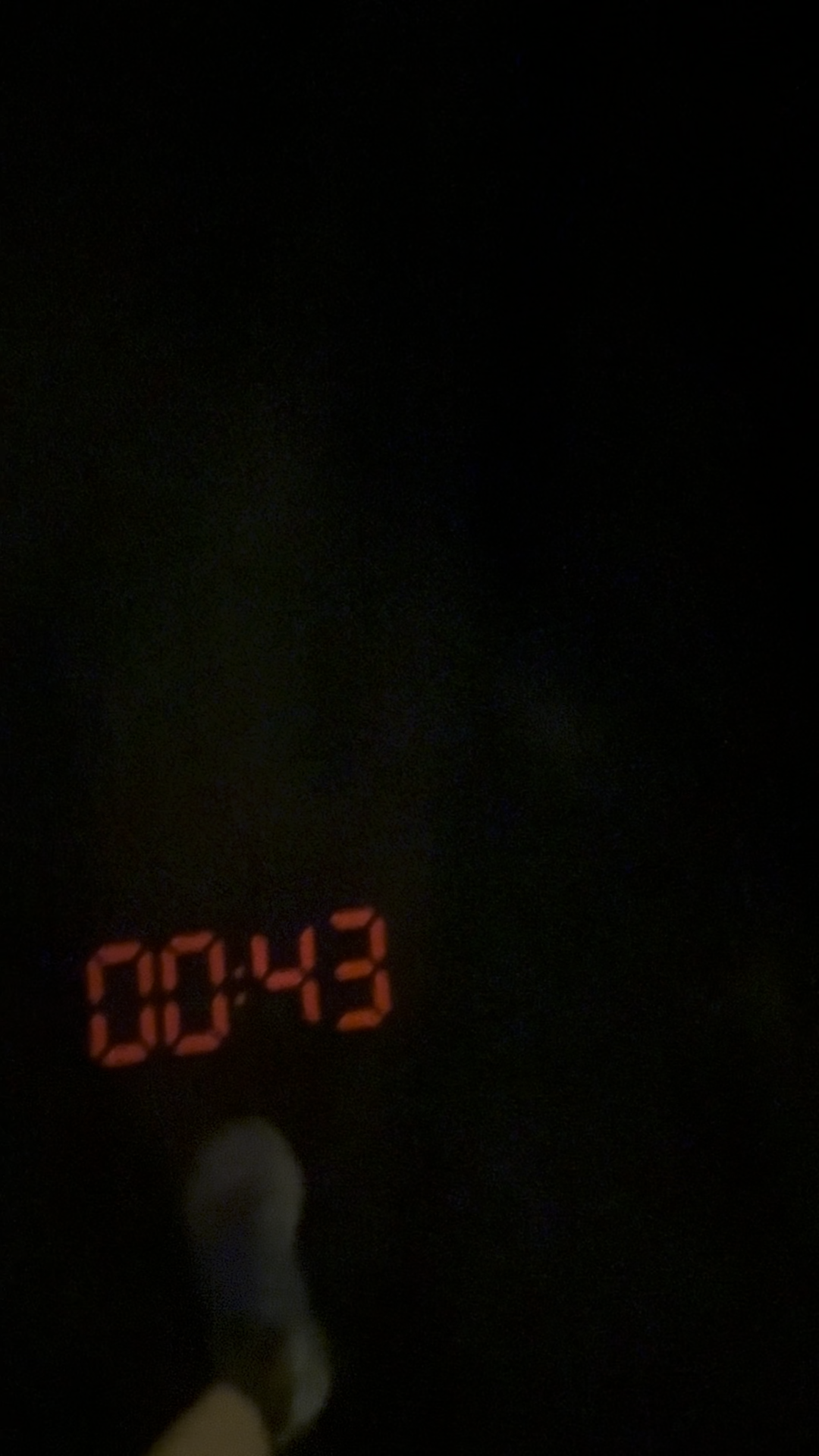
Timer format. The stopwatch shows MM:SS packed as a four-digit number — 0132 for 1 minute 32 seconds. The colon is a separate segment, handled by the com | 8 line in printSingleNumberTimer().
Button logic. The 400ms timeout separates single from double click. Long press only fires on a continuous hold — you can’t accidentally trigger it.
The first run
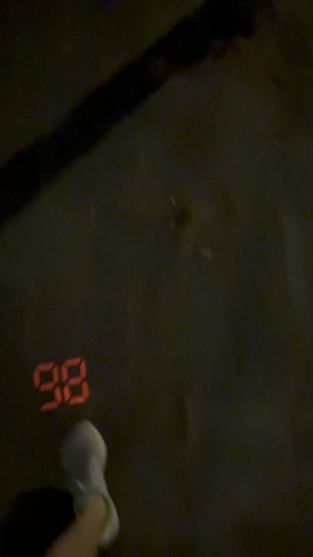
More than a month after first unscrewing that alarm clock, I went out with an ESP32 taped to my chest, the projector module mounted in front of me, and the BLE strap doing its job.
Two things I hadn’t anticipated: the vibration from running made the projected digits shimmer slightly on the surface, and you need it dark enough outside for the numbers to be readable — bright daylight washes them out. Both are fixable; neither killed the concept.
What wasn’t fixable — because it didn’t need fixing — was watching the heart rate climb as I pushed harder and drop as I eased off, in real time, without moving my wrist once. The stopwatch was genuinely useful too: knowing elapsed time without breaking stride is a small thing until you’ve had it, and then you can’t go back.
 |  |
|---|
It wasn’t a polished product. The cables were held together with electrical tape. But the core idea — data that comes to you instead of the other way around — was completely validated.
No lifting my wrist. No waiting for a screen to wake up. No breaking stride. The numbers were just there, on the wall in front of me — exactly where I’d wanted them from the start.

Lodovico Cortelazzo
Former national-team athlete. 15 years of training. Exercise science and engineering.
Fifteen years of training, eight at national level, give a specific kind of eye for what sport technology actually does versus what it claims to do. I combine a background in exercise science with hands-on engineering to build and analyse tools that are meant to work in the real world. If you are working on something in this space and want that perspective, reach out.
Work with me →