How I Turned a Cheap Alarm Clock Into a Heads-Up Display for My Runs (Part 1)
The problem: my data was always one second too late
I run. A lot. And like most runners, the two numbers I care about while I’m moving are dead simple: elapsed time and heart rate.
The thing is, getting those numbers was never as simple as it should be. I’d be mid-run, lungs working, legs ticking over, and I’d want a quick glance at my watch. But “quick” was never quick. I’d lift my wrist, rotate it into view, and then… wait. Because nine times out of ten the screen was off. So I’d stand there (or worse, keep running and stumble) waiting for the display to wake up, find the right screen, and finally show me a heart rate that was now a few seconds stale.
What was supposed to be a glance had become a little ritual: lift, twist, wait, squint. It broke my rhythm every single time.
So I started thinking about it the way an engineer thinks about anything annoying: the interface is wrong. I didn’t want to go to the data. I wanted the data to come to me — sitting right in front of my eyes, always on, no wrist-lifting, no waking up a screen.
The idea crystallized: project the numbers I need directly in front of me. Elapsed time and heart rate, floating there, always visible.
The easy half: getting heart rate
Heart rate turned out to be the trivial part of this whole project, and that’s thanks to a wonderful little piece of standardization.
Almost every modern fitness chest strap speaks BLE (Bluetooth Low Energy), and — crucially — most of them implement the standard Heart Rate Service. That means I didn’t have to reverse-engineer anything: there’s a published GATT profile, a known service UUID (0x180D) and a known characteristic (0x2A37) that streams beats-per-minute. Plug-and-play, more or less.
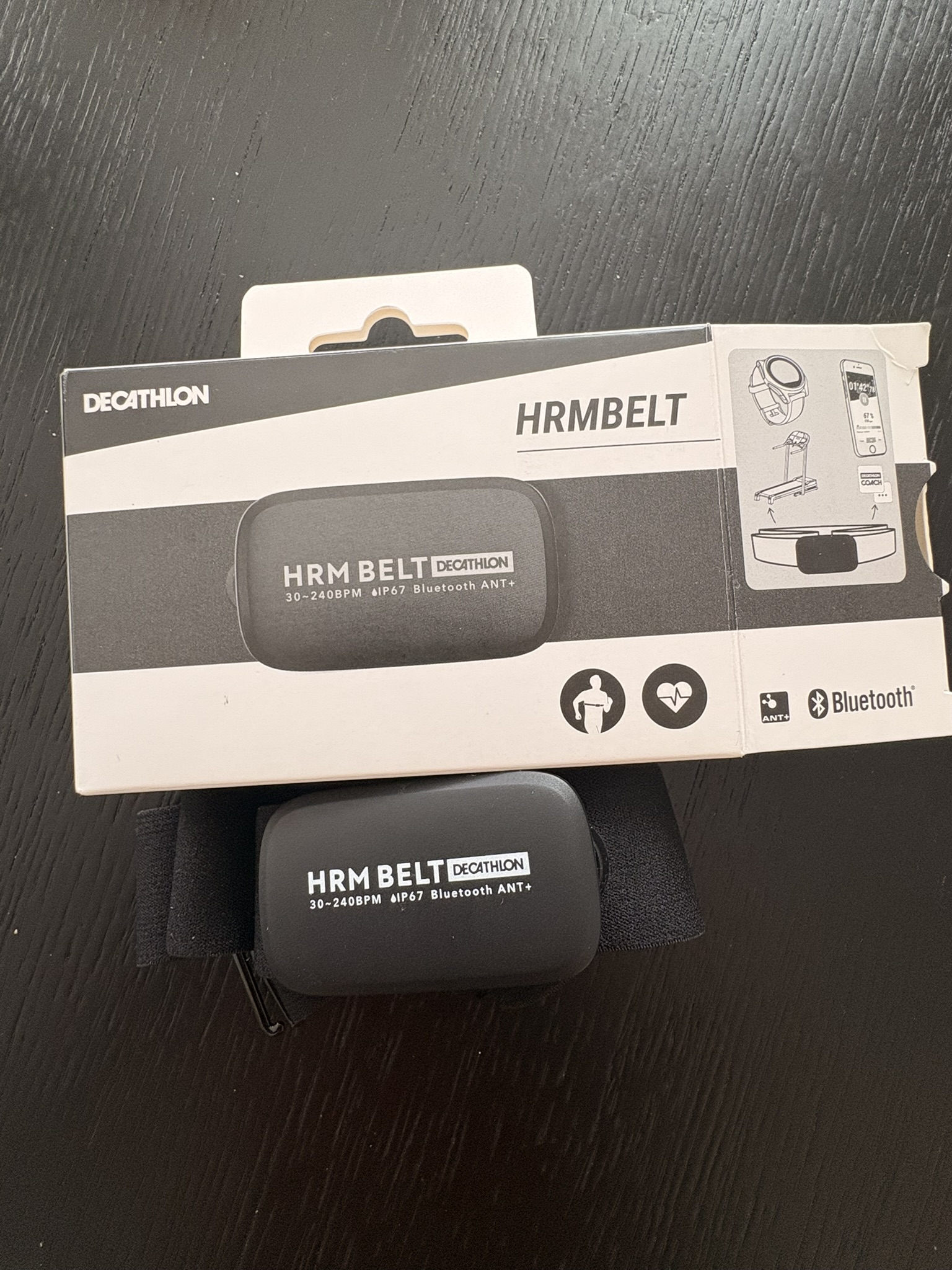
So I went down to Decathlon and grabbed a basic BLE heart-rate strap. Nothing fancy — the cheapest one that advertised Bluetooth.
An ESP32 with its built-in Bluetooth radio connects to this thing almost immediately, as long as you’ve got the right code. Here’s a deliberately stripped-down example just to show how little it takes to subscribe to heart-rate notifications using the NimBLE library:
#include <NimBLEDevice.h>

// Standard BLE Heart Rate Service + Measurement characteristic
static NimBLEUUID hrServiceUUID("180D");
static NimBLEUUID hrCharUUID("2A37");

uint16_t currentHR = 0;

// Called every time the strap pushes a new measurement
void hrNotifyCB(NimBLERemoteCharacteristic* chr,
                uint8_t* data, size_t len, bool isNotify) {
  if (len < 2) return;
  // First byte = flags. Bit 0 tells us if HR is 8-bit or 16-bit.
  if (data[0] & 0x01) {
    currentHR = data[1] | (data[2] << 8);   // 16-bit value
  } else {
    currentHR = data[1];                     // 8-bit value
  }
  Serial.printf("HR: %d bpm\n", currentHR);
}

void setup() {
  Serial.begin(115200);
  NimBLEDevice::init("");

  // Scan, connect to the first device advertising the HR service,
  // grab the characteristic, and subscribe to notifications.
  NimBLEScan* scan = NimBLEDevice::getScan();
  NimBLEScanResults results = scan->getResults(5 * 1000);

  for (int i = 0; i < results.getCount(); i++) {
    const NimBLEAdvertisedDevice* dev = results.getDevice(i);
    if (dev->isAdvertisingService(hrServiceUUID)) {
      NimBLEClient* client = NimBLEDevice::createClient();
      if (client->connect(dev)) {
        auto* svc = client->getService(hrServiceUUID);
        auto* chr = svc ? svc->getCharacteristic(hrCharUUID) : nullptr;
        if (chr && chr->canNotify()) {
          chr->subscribe(true, hrNotifyCB);
        }
      }
      break;
    }
  }
}

void loop() {
  // currentHR is now updated in the background, every heartbeat-ish.
  delay(1000);
}
That’s it. The strap broadcasts, the ESP32 listens, and currentHR is always sitting there with a fresh number. Half the project, basically solved on day one.
The other half — how do I actually throw these numbers in front of my face? — is where things got interesting.
The fun half: how do I project the data?
I sat with the “display” problem for a while. A normal screen wouldn’t cut it — I’d be right back to lifting and squinting. I needed something that put the numbers out there, on a surface, big and always-on.
And then a memory surfaced. When I was a kid, we had one of those novelty alarm clocks that could project the time onto the ceiling — big red numbers glowing up there so you could roll over at 3 a.m. and read the time without moving.
That’s it. That’s the whole mechanism I needed. A device that already knows how to take some digits and throw them, glowing, onto a surface in front of me.
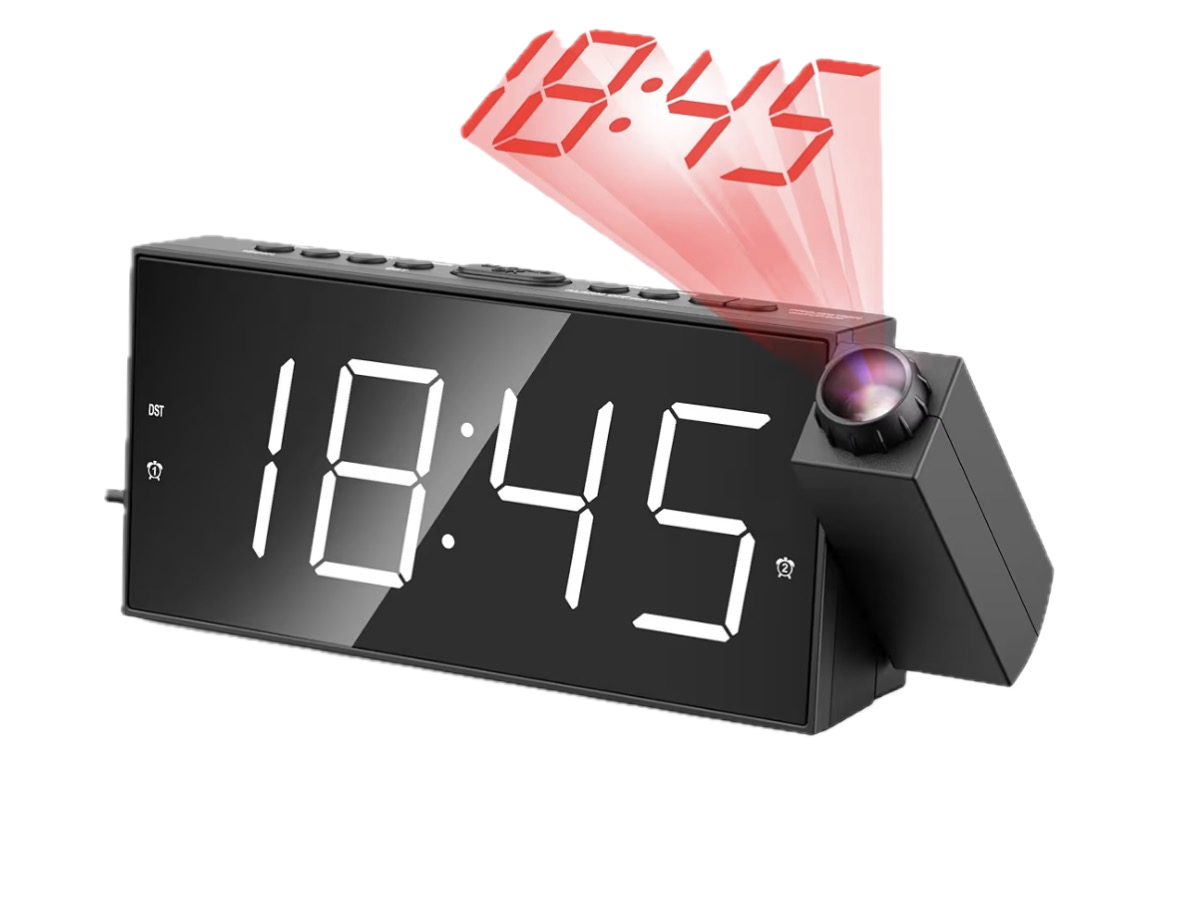
So I went to Amazon and bought the cheapest projection alarm clock I could find.
Cracking it open: two clocks in one box
Here’s the first pleasant surprise. When I disassembled the clock, I discovered it wasn’t one integrated unit — it was effectively two separate modules bolted together:
- The alarm clock itself, with its own front-facing LCD display.
- The projector module — a separate little assembly with the LED, the lens, and its own number display that gets thrown onto the wall.
That second module is the juicy part. I don’t care about the clock’s own front screen. I care about the thing that projects digits. If I could hijack just that module and feed it my own numbers, I’d have my heads-up display.
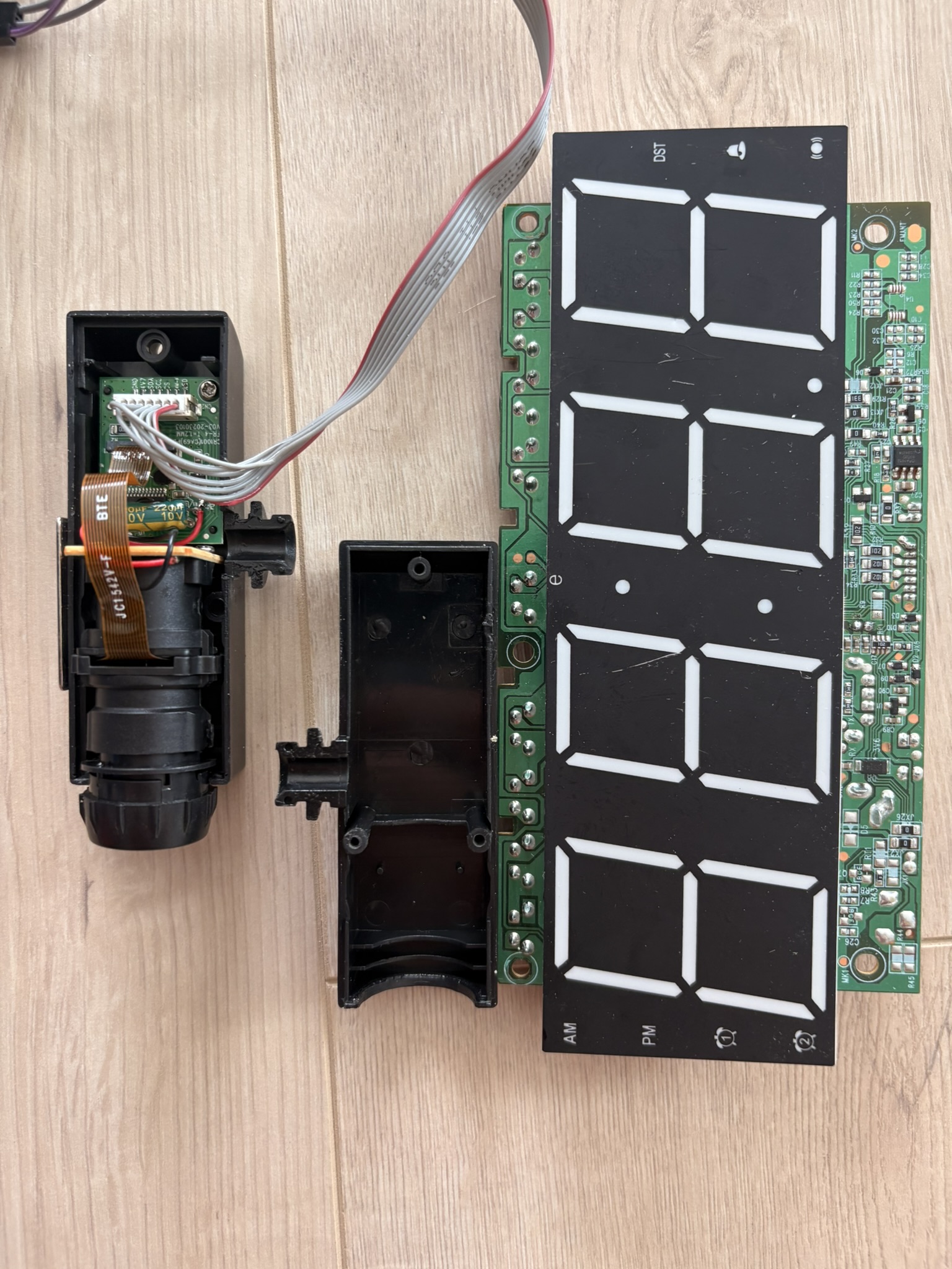
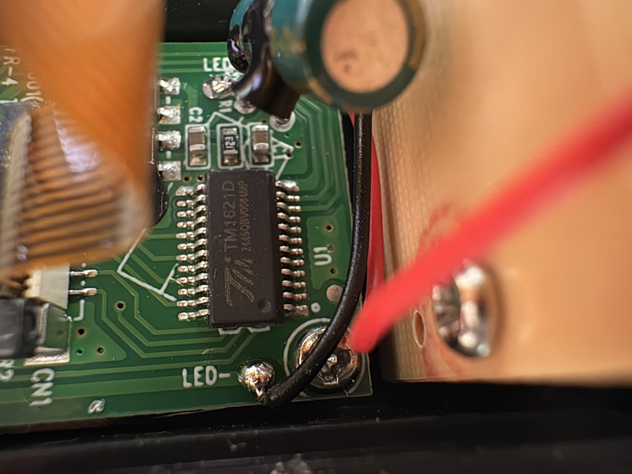
When I separated the projector module from the main board, I found the two were connected by a small ribbon: seven wires.
Seven wires. That’s the whole conversation between the clock’s brain and the projector. If I could understand what those seven wires were saying, I could say it myself.
Reading the tea leaves: what do these seven wires do?
This is the part of any reverse-engineering project where you either get lucky or you get out the oscilloscope and prepare to suffer.
I got lucky.
Printed right on the PCB, next to the connector, were silkscreen labels for each pin. Whoever designed this board left the breadcrumbs for me:
- GND — ground, the reference everything else is measured against.
- 4.7V — the power rail for the projector module.
- SDA — serial data.
- SCL — serial clock.
- CS — chip select.
- DIM-K — dimming control (brightness of the projected display).
- LED — control for the projection LED / backlight.
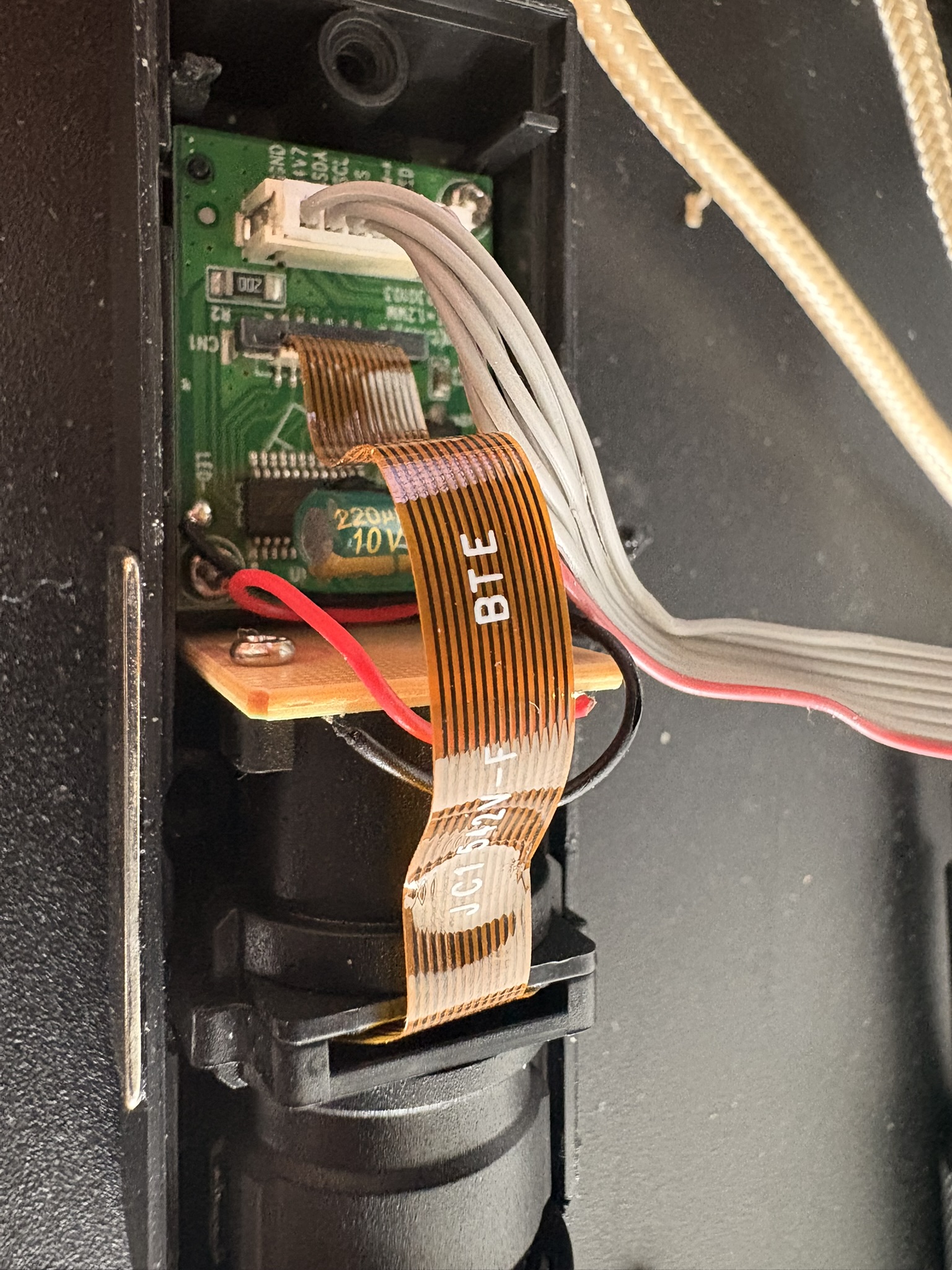
The moment I read those labels, the fog lifted. GND and 4.7V are just power. DIM-K and LED are about how bright the thing glows. That leaves three pins — SDA, SCL, and CS — doing the actual talking. And those three names are a dead giveaway: this is a synchronous serial bus, data + clock + chip-select. We’ll come back to exactly which flavor in a second.
Following those data lines, they all converge on a single chip: a TM1621D.
Meet the TM1621D, the chip that runs the show
The TM1621D is an LCD driver / controller — a dedicated little IC whose entire job is to take commands and display data from a microcontroller and turn them into the right pattern of segments lit up on an LCD.
A few things worth knowing about it:
- It’s a segment LCD driver, designed to drive the kind of multi-segment LCD you find in clocks, thermometers, and cheap appliances — the panels made of fixed segments (like the seven-segment digits) rather than a pixel grid.
- It has its own internal display RAM. You don’t continuously refresh the screen yourself; you write the segment data into the chip’s RAM, and the TM1621D handles the constant multiplexing and driving of the LCD for you. Set it and forget it.
- It runs on a tiny serial interface using exactly the lines we found: a data line, a clock line, and a chip-select line.
- It accepts a handful of command words (to turn the display on/off, set the bias/duty, configure the internal oscillator) plus data writes that target specific addresses in its display RAM.
In other words, this chip is the gatekeeper. Whatever digits appear in that projection are decided by what gets written into the TM1621D’s display RAM. Control the writes, control the display.
So which protocol is it? SPI (sort of)
Given the three signal lines — data, clock, and chip-select — the communication looks like SPI, and for our purposes we can treat it that way.
Quick refresher on SPI (Serial Peripheral Interface) for anyone who hasn’t bit-banged one at 2 a.m.: it’s a synchronous serial protocol, which means data is shifted out one bit at a time, and every single bit is paired with a tick of a clock line so both sides agree exactly when to read it. The classic SPI lines are:
- a data line (the controller pushes bits out on it),
- a clock line (
SCL/SCK— one pulse per bit), and - a chip-select line (
CS— pulled to its active level to say “hey, this message is for you, start listening”).
The dance is always the same: assert chip-select, then for each bit, put the bit on the data line and pulse the clock so the chip latches it, repeat for all the bits, then release chip-select to end the message. There’s no addressing, no acknowledgments, no handshaking — just “here are the bits, here’s the clock, catch.”
The TM1621D’s interface isn’t textbook-perfect SPI (it has its own command/data framing and is technically a 3-wire variant), but the fundamental act is identical: clock bits out, one at a time, MSB-first, while holding chip-select active.
Which brings me to the single most satisfying function in this entire project — the Holy Grail. Once I had this working, everything else was just figuring out which bits to send. This is the function that physically shifts a chunk of data out to the chip:
void lcdShift(unsigned long data, int bits) {
  unsigned long bitmask = 1UL << (bits - 1);
  digitalWrite(latchPin, LOW);
  for (int i = 0; i < bits; i++) {
    digitalWrite(clkPin, LOW);
    digitalWrite(dataPin, (data & bitmask) ? HIGH : LOW);
    delayMicroseconds(2);
    digitalWrite(clkPin, HIGH);
    delayMicroseconds(10);
    bitmask >>= 1;
  }
  digitalWrite(latchPin, HIGH);
  delayMicroseconds(2);
}
Let me walk through why this is the Holy Grail, line by line, because it’s beautifully simple once you see it:
unsigned long bitmask = 1UL << (bits - 1);— we build a mask with a single1in the most significant position of however many bits we want to send. This is how we shift out MSB-first: we’ll walk this single1from left to right.digitalWrite(latchPin, LOW);— we assert chip-select (here calledlatchPin). Translation: “TM1621D, listen up, a message is coming.”- Inside the loop, for each bit:
digitalWrite(clkPin, LOW);— drop the clock low to prepare the next edge.digitalWrite(dataPin, (data & bitmask) ? HIGH : LOW);— set the data line to the current bit.data & bitmaskisolates exactly the one bit we’re on.delayMicroseconds(2);— let the data line settle so it’s stable before the clock edge.digitalWrite(clkPin, HIGH);— the rising clock edge. This is the moment the chip samples the data line and latches the bit.delayMicroseconds(10);— hold it so the chip has time to register it.bitmask >>= 1;— slide the mask one position right, moving to the next bit.
digitalWrite(latchPin, HIGH);— release chip-select. “Message over.”
That’s the entire physical layer. Notice that I’m generating the signal in software: the ESP32 has a dedicated hardware SPI peripheral that could shift these bits out for me, but instead I’m toggling the clock and data pins by hand with digitalWrite(). This approach is called bit-banging. It’s perfect here because the timing is gentle and I get total control over the framing — exactly what you want while you’re still reverse-engineering an unknown chip.
The reason I call it the Holy Grail is simple: the moment this function worked, I could put any bit pattern into that chip. I could make segments turn on and off at will. The hardware was no longer a mystery box — it was an output device I owned.
Where we are, and what’s next
Let’s take stock of what we’ve got at the end of Part 1:
- A clear problem: data that’s always a beat too late, and an interface (the wrist-flick) that breaks my running rhythm.
- The easy half solved: a BLE heart-rate strap + an ESP32 that gives me a live
currentHRvalue with almost no effort. - A cheap projection alarm clock torn open to reveal a self-contained projector module.
- Seven wires demystified by the PCB’s own labels, leading to a TM1621D LCD driver.
- And the Holy Grail function —
lcdShift()— that lets me push arbitrary bits straight into that chip.
But here’s the catch, and it’s a big one: being able to send any bit pattern is not the same as knowing which bit pattern lights up which segment. Right now I can shout at the chip in its native language, but I don’t yet know the vocabulary. Sending random data just makes random nonsense glow on the wall.
Part 2 is all about the mapping — the painstaking, oddly addictive detective work of figuring out exactly which bit controls which segment of which digit, so I can go from “I can light up something” to “I can write the exact number 142 bpm on my wall.” That’s where the project goes from hardware hack to actual training device.
See you in Part 2. 🏃
Next up — Part 2: Mapping the segments, or how I taught a broken clock to count.
Building something in sport-tech and want a second opinion?
Work with me →